Short theory about Surface (Ground) Effect
 The effect of placing a fixed surface near an airfoil has many interesting complications. The most obvious is the addition of something to crash into. This “obvious” issue suggests driving a WIG-craft resembles landing an aircraft more than flying one, but the addition of the surface also adds benefits. The surface interferes with the air flow patterns around the wing, and a possibility exists to use this interference to a WIG-craft’s benefit.
The profile of a wing is designed to create low pressure above and high pressure below. This generates lift for the craft, but air will take the easiest path to pressure equalization, so the air also flows around the tip of the wing. This flow of air around the wing tip requires energy. Since these spinning vorticies of air yield no useful benefit, The energy must be spent, but is essentially lost or wasted (wing tip vortices drag). Reducing this energy loss creates a more efficient craft. Surface Effect theory suggests that we use good old fashioned dirt (or water) as a tool to interfere with, and thereby reduce, these vorticies (these losses).
Tip Vortices Drag Reduction (Span dominated Surface Effect)
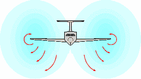
 The graphic to the left shows the surface interfering with the lateral airflow. This will reduce energy spent (wasted) creating the tip vortices, and there by reduce the induced drag. This Effect is commonly referred to as Span Dominated Surface Effect because the effect/benefit is proportional to Span. (h/b or Span/Height)Ram Air (Cord Dominated Surface Effect). If the wing was infinitely long, there would be no tip and no vortex. The wing woul extend beyond the stratosphere as well, so lets consider something more realistic. I glider with a 60ft span, uses span/Aspect ration to reduce vortex. Since this craft has smaller than average vortex generation, flying close to the surface will also yield less vortex reduction. A fighter jet, on the other hand, with its very low aspect ratio will experiance much greater (relative to average) vortex reduction.
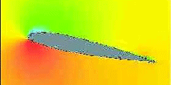
 Pictured is a 2 dimensional depiction of a Pressure Distribution around a Wing moving through free air. The Green area above the wing shows the location of maximum suction (upper surface). The red below the wing shows the red area shows the location of the maximum pressure (lower surface). The yellow area is the atmospheric pressure. Note also that both the non-yellow areas appear to be centered nearer to the leading edge of the wing (around the 25% cord), and that both sucking the upper surface and pressure on the lower surface result in upward force. This lifting force is typically centered around the 1/4cord.
The streamlines, show the disturbed air (ie drag). Note that air disturbance extend forward, beyond the front of the wing.
WIG lift with the Wing in Surface effect
 When air flows around a wing in close proximity to a surface, the flow is altered/restricted by the surface. This is true all the time, but we are only interested in the events where the surface is below the craft such as water or land. There are 3 inter-related effects that occur to in this flow as we compare it to the flow in free air.
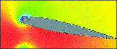
When the flow on the flow on the underside of the wing is restricted. The flow on the upper surface experiences less positive pressure gradient. The impact on pressure gradient results in slower flow over the upper surface, which can be seen by the reduced green area over the wing. The impact on pressure gradient will also allow separation (stall) to occur at an lower angle of attach.
Secondly, the red area below the Lower surface is increased in size, and has moved aft on the wing to nearer to the center of the wing. Reducing the upper surface lift, and increasing the aft portion of the lower surface lift will result in a lateral shift of the center of lift. A craft balanced for free air flight will experience an nose down moment when it transitions into surface effect. Similarly, and craft balanced for surface effect will experience a nose up moment when transitioning out of surface effect.
Span wise flow is restricted, making the wing function more like an infinite span wing.
1. Span wise flow is restricted, reducing the tip vortex, and allowing the wing to function more like an infinite span wing.
2. In extreme proximity air below the wing is trapped (to some degree) reducing the cord wise Lower Surface flow, and increasing the static pressure.
3. The reduced Lower Surface flow has a reduced (pulling) effect on the upper surface flow. The reduced “pulling” on the upper surface flow reduces the pressure gradient in the flow. Reducing the energy in the flow negatively impacts the energy; as a result the Upper Surface flow separates from the wing at a lower angle of attack than would occur in free air. (earlier on set of stall in GE)
4. In some circumstances, depending on wing profile, a venturi may develop between the wing and the ground. This will accelerate the air flow beneath the wing. The negative effect on lift of this venturi flow can over come the benefit of the air being trapped. In extreme cases, the net aerodynamic lift can even be negative.
Ram Air (Cord Dominated Surface Effect)
A second form of energy loss is that of compressing air, only to let it expand again after the wing has traveled past. Pressure is lost when the high pressure directly below the wing compresses the layer of air beneath it, and that layer compresses the layer beneath it and …. Compressing all this air means more lost energy. Again, Surface Effect Theory suggests that we use good old fashioned dirt (or water) as a tool to interfere with (thereby reduce) these losses. Adding a fixed (non-compressible) surface, stops the movement of air down.
Comparing the two pressure graphics, shows that the wing in Surface effect produces approximately double the amount of lifting force as the wing in free air. It is widely published that this effect is directly proportional to the cord length (x) and inversely proportional to elevation (h) and is know as Ram Effect, or Cord dominated Surface effect.
As a result, a WIG-craft of comparable size should be able to transport almost double the weight of an aircraft. The increased pressure on the lower image can be clearly observed, and a much “cleaner” air stream around the wing is also evident.
Avoiding the venturi issue, and using the combination of the first two effects, (reduced drag and increased lift) provides the carrot that we chase in terms of a more efficient craft. Unfortunately, the ground effect comes with more obstacles than just a avoiding flying to low.
Longitudinal stability
The “center of effort” (CE) of a wing and the “center of gravity” of the craft have to be in the same plane (with some margin), for both aircraft and WIG-craft.
The pressure distribution images also demonstrate that the pressure around a wing in free flight and a wing in Surface effect are different. The CE of a wing in free flight is at about 25% cord length, and the CE for the same wing in Surface effect is at about 45% of cord length.
The result can be disastrous when a WIG-craft, balanced for Surface effect, flares out of ground effect. As the craft separates from the ground, the CE moves forward on the wing and the nose wants to pitch up. To compensate for this, WIG-craft need horizontal stabilization.
For the four main craft-types, the effect is more or less pronounced.
The Joerg tandem WIG design is not effected by this phenomena because the craft is supported by two (front and rear) wings. As the craft’s nose lifts, the front wing moves into free air (reduced lift) but the rear wing remains in Surface effect (maintains GE lift). The reduction of lift on the front wing acts as a stabilizing force. Thus vertical stability is incorporated into the design, and no additional horizontal stabilization is needed.
Note however that experience has shown that when of this type of craft flares out of ground effect, disastrous instability awaits.
The reversed delta wing (Professor Lippisch design) has a single triangular shaped wing with the small end to the rear of the craft. This shaping of this wing is more conducive to stability, but because the design utilizes only one wing, these craft have small horizontal stabilizers.
The single, low aspect ratio, square wing is highly affected this problem, so Ekranoplans and derivatives require very large horizontal stabilizers. They also use S shaped foil profiles to aid in stabilizing the Craft. In my experiments, I have not found a single S shaped airfoil that did not suffer from the development of venturies. As a result, these Wings should never be used in Extreme Gorund Effect.
For more information on WIG theory go to the WIG-page or to the Fischer Website.
